Interface Paradigms for Pathway Model Builders
Converting a biochemical reaction network to a set of kinetic rate equations is tedious and error prone. The initial conceptual entity for most modelers when developing a model is the wiring diagram. A wiring diagram nicely represents the topology of a reaction network (reactants, products, enzymes).
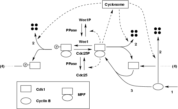
But one cannot also specify the kinetics of the network (the reaction rate laws, vj) adjacent to the reaction arrows without cluttering the diagram beyond recognition. A large reaction network can become so complex that even its topological features are obscured by a large number of intersecting arrows. For example, a realistic model of the budding yeast cell cycle consists of about 30 differential equations containing 100 rate constants. To adequately describe fundamental physiological processes (such as the control of cell division) in mammalian cells will require models of at least 100-1000 equations.
Obscurity is increased further because there is no standard format for drawing such graphs, though Kohn's notation has much to recommend it. Without precise notational conventions, it is impossible to convert a wiring diagram into an unambiguous model, either by hand or machine.
A second method for representing a reaction network is to explicitly write out the chemical reactions, S1, ..., Si into products P1, ..., Pj. This loses some of the intuitive appeal of the diagrammatic approach, but allows for a more compact definition of a reaction network. Normally, the modeler has already made a hand or CAD-drawn version of the network in graphical form, showing the interactions in a qualitative sense but without the quantitative information of the velocity equations or the parameter values.
We have identified three distinct paradigms that have been used by user interfaces for existing model builders.
Graphical Interfaces: Virtual Cell, JDesigner, and Bio Sketch Pad (BSP) are examples of a user interface for specifying a model as a graphical network. In Virtual Cell, for example, the network is created in a workspace where a species is represented as a circle and a chemical reaction is represented by a barbell. Substrates are connected to the left end of the barbell and products to the right end. Catalysts are connected to the middle of the barbell. Right clicking the barbell generates a dialog box that allows a user to enter the velocity of the reaction. The mass action rate law is given as a default, with a locally defined rate law being allowed but no global user-defined rate law may be specified.
With all existing diagram editors, as the model grows, an increasing fraction of the graph's edges cross one another, leading to confusion for the user. Ideally, model complexity would be dealt with by some bundling mechanism whereby sections of the graph can be replaced by a single icon, to be contracted or expanded as desired. To date, no graphical editor for regulatory network models supports such bundling.
Users must typically resort to some alternative interface for entering the inherently textual information required to specify the reaction equations. No existing graphical interfaces are purely graphical for this reason. Entering the various parameter values and rate equations can account for a significant fraction of the total model description.
Wizard Interfaces: The ``wizard'' metaphor consists of a series of dialog boxes that lead a user through the various stages of creating a reaction network. Wizard interfaces are a well-known approach for guiding users through a highly structured and well-defined task, such as entering information required for installing software or hardware in Microsoft Windows. Gepasi exemplifies the wizard interface for regulatory modeling. First, the user enters the chemical equations for a network by selecting the reactions button. Next, to specify the velocities of the equations, the user clicks the kinetics button and selects the rate law to use for the chemical equation. To add a user-defined rate law the user must go back to the previous screen and click the kinetic types button and choose the add button. User-defined functions are specified in a similar manner by clicking on the functions button and choosing the add button.
The advantage of the wizard interface is that it guides the user through the model-building process. This provides more support for users unfamiliar with either the tool or the modeling process. However, a wizard interface breaks the model representation (and the model building process) across many screens. As a consequence, models are difficult to visualize as a whole when using the wizard paradigm. Hence the modeler might lose focus on the full model, and be distracted by navigating through a series of dialogs showing only detailed portions of the model at any instant. The wizard approach is likely to lead to more mouse clicks and movement than would be necessary in an interface more tuned to an experienced user, so is inherently inefficient to some degree.
Text-based Interfaces A third approach for building reaction networks is direct editing of the collection of reaction equations, expressed in ASCII text. Examples of this approach are SCAMP and Jarnac.
Jarnac uses a compact text-based scripting language similar to the specification of chemical equations. A large model can be specified quickly and can be compartmentalized. Compartmentalized models become models unto themselves, able to be viewed as a black box with inputs and outputs. This removal of data overload allows the user to more easily visualize large models. Because Jarnac uses a programming language-like form it is compact and precise. However, the concept of ``programming'' the model is likely to be unnatural for many life scientists.
No system is entirely restricted to one paradigm. Virtual Cell uses a scripting language to make up for limitations to its graphical interface. BSP uses a wizard interface for entering rate laws. Some systems attempt to combine the strengths of the graphical approach with the equation editing approach. Jarnac works in combination with JDesigner (JDesigner is intended as a graphical front end to Jarnac).
With the JigCell Model Builder (JCMB), we introduce an important variation on the text-based approach. JCMB specifies reaction networks using a spreadsheet paradigm. Biologists are more likely to be experienced with creating spreadsheets than with creating programs or scripts. The spreadsheet approach also has the advantage that it imposes more structure onto the equation-writing process than a scripting language.
JCMB mimics the standard functionality of a spreadsheet, with each reaction, function, and rate law being defined on a separate row.